Chemical reactions, which take place owing to higher temperature and pressure requirements ranging up to 260 °C / 200 bars, are the applications for which Berghof reactors are designed. The special feature of Berghof reactors is their unique, thick PTFE liner. All the parts, which come into contact with liquid media, are either made entirely from PTFE or they are coated with a fluoropolymer.
Corrosion protection included
A PTFE liner, which is several millimetres thick, protects the stainless steel reactor efficiently against corrosion, even against such corrosive media as acids and alkali. PTFE is distinguished by its excellent resistance to almost all chemicals, which makes it possible to do without many expensive special alloys, such as hastelloy. This significantly reduces the acquisition costs. The risk of possible cross-contaminations is easier to control with PTFE liners. Metallic catalysers , such as Pt, Rh, Raney Nickel etc adhere to steel reactors and are very difficult to remove. In the following experiments the question keeps cropping up if the effects observed are really caused by the change of catalyser, contamination effects or catalyst poisoning. This problem is elegantly evaded by reserving a PTFE liner for each type of catalyser.Tip: The PTFE liners can also be used as practical storage vessels for reactive solutions.
Universal usage
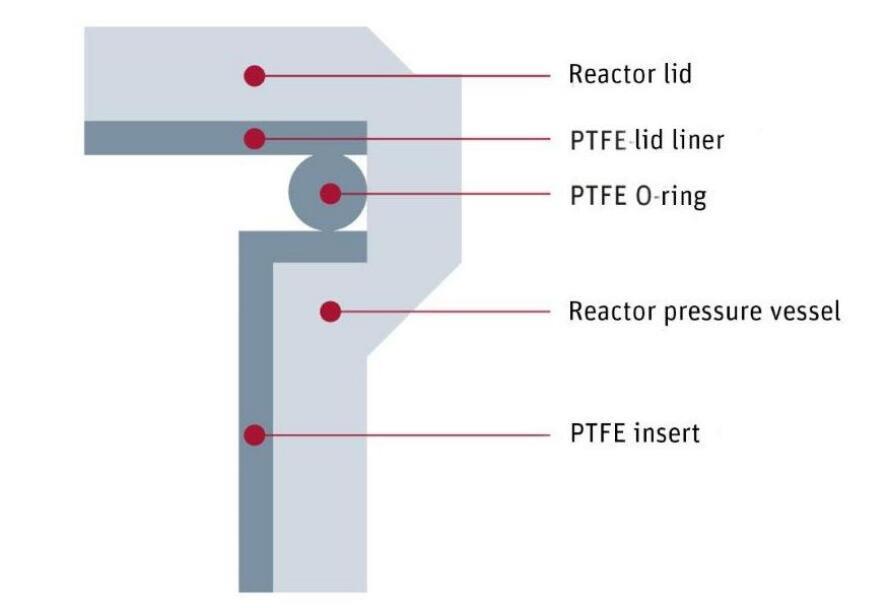
Berghof reactors can be used for all purposes; all of the parts that come into contact with liquid phase are protected against chemical attack by means of fluoropolymers. The liner is hermetically sealed and clings to the inside of the reactor wall like a skin. Hence it differs significantly from the PTFE liners, which are placed open into the reactor. The entire liner comprises a removable PTFE insert, the cover lining, the dip pipe and agitator sheaths and the PTFE sealing rings. All of these parts can be removed and remounted easily for cleaning purposes. The thickness of the walls of the liner depends on the reactor volume and ranges between 1.6 and 7.4 mm. The lining of the cover is at least 3.7 mm thick. The maximum operating pressure of the reactors is 200 bars and the maximum temperature for continuous operation is 230 °C. For a short time (i.e. max. 60 min) the reactor can also be heated up to 260 °C. Higher tempera-tures and longer heating phases above 260°C damage the PTFE liner. Owing to these high operating temperatures, conventional PTFE components become “distorted”; but Berghof components do not. These PTFE components have no preferred direction because, thanks to the isostatic compression-molding method developed by Berghof have no preferred direction and distinguish themselves by the same expansion coefficients in all directions in space. A “distortion” of the parts, even at a higher temperature and pressure is thus excluded.

Advantages of PTFE-lining:→ High tempering strength, briefly up to +260 °C→ Pressure-tight up to 200 bars→ Universal resistance to chemicals, even to aggressive acids and alkali→ Non-corrosive→ Free of contamination
Isostatic compression molding
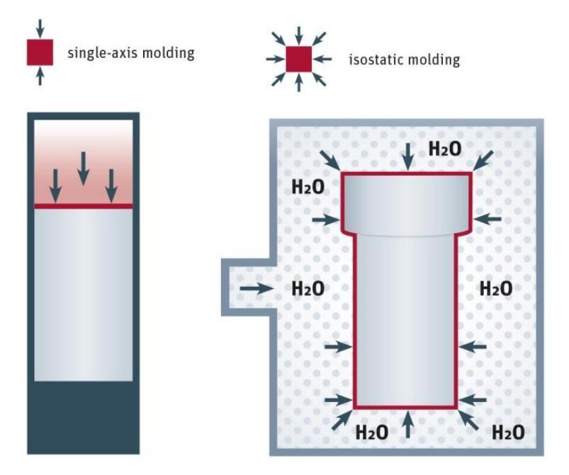
B When conventional, single-axis compression molding methods are applied, as a rule the material is compressed vertically in a mold with a force plug. There is no horizontal compression crosswise to the compression direction. By contrast, in the isostatic compression-molding process the force is applied to the material evenly and simultaneously from all directions in space via a hydraulic medium and compresses it homogeneously. Hence optimal compression is achieved, resulting in minimal porosity, a better surface structure and maximum tensile and compression strength. No preferred directions are created and isotropic material properties are retained. Particularly the tensile and compression strength of the material is consistent in all directions in space.

Quality advantages thanks to isostatic compression molding
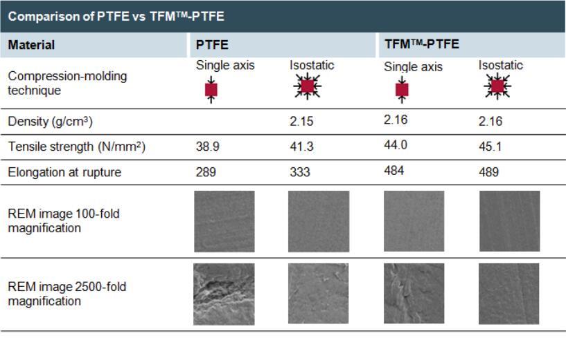
The advantages of isostatic compression molding can be illustrated by means of appropriately enlarged REM images. When magnified 100 times the granulate particles of the original material can still be identified in PTFE if it has been subjected to single-axis compression molding. By contrast, isostatically compression-molded PTFE shows a significantly more consistent surface structure. It is roughly equivalent to single-axis compression-molded TFM™PTFE. However isostati-cally compression-molded TFM™PTFE achieves a much finer and smoother structure. Furthermore, when magnified 2,500 times, in single-axis compression-molded material flaws become visible, which no longer occur in isostatically compression-molded TFM™PTFE.

Post time: Apr-10-2020

